(603)-742-8812
Established In 1981
CNC Engine Block Decking Surfacing & Squaring
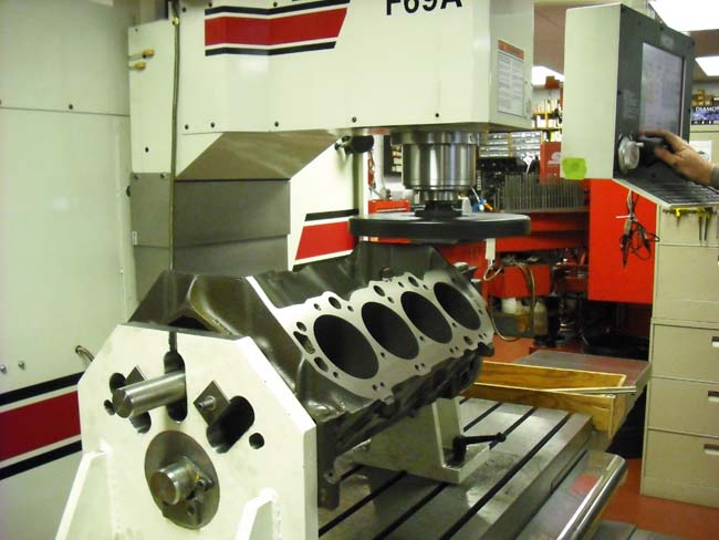
Our Datum Plates Locate From The Main and Cam Line
Left Bank Decked Precisely at 45 degrees
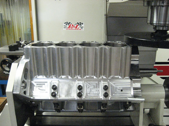
Our Datum Plates Locate From The Main and Cam Line
Right Bank Decked Precisely at 45 degrees
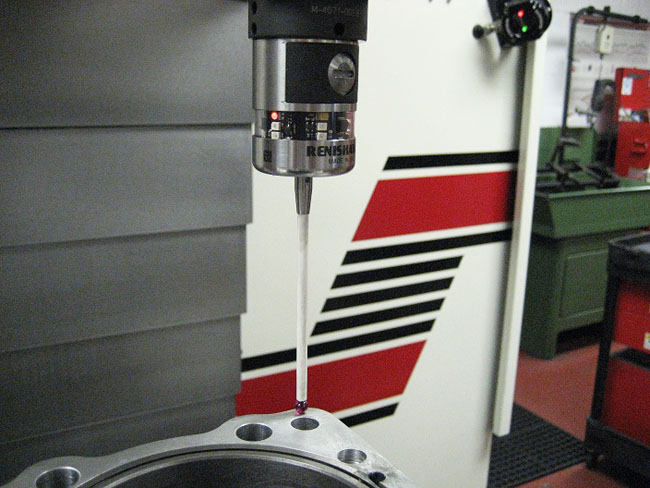
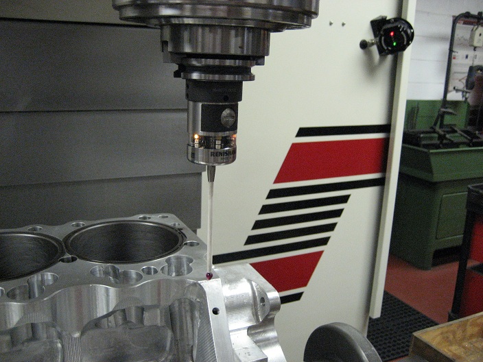
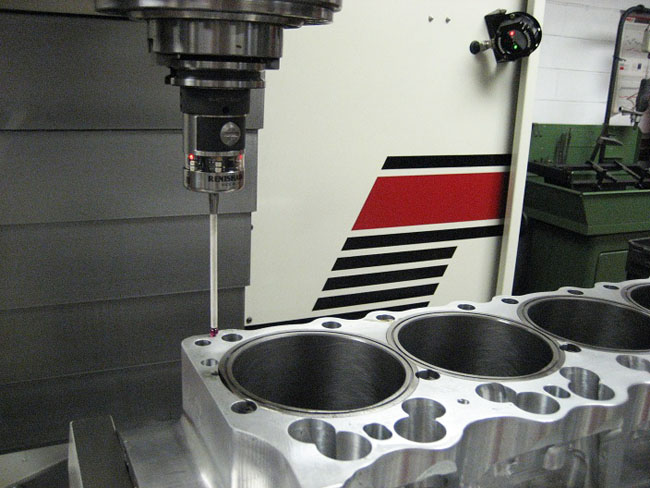
CNC Engine Block Probing Routing determines how much material To Remove To achieve desired deck height
Sqaure decking right bank
Sqaure decking left bank
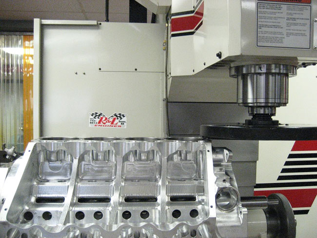
Surfacing engine block intake runner
Engine Block Decking Defined
The term decking is used for the machine process that trues the head-gasket surface of the block. Most of the time, the objective of decking is to end up with a flat surface cut that is parallel with the center line of the crankshaft and at the correct angle to the cylinder bores. Another use for this procedure when building a V-8 is to make sure the surface of each deck is the same distance from the crankshaft. Decking can also be used to increase the compression ratio by reducing the quench volume and bringing the piston closer to the top of the bore when at top dead center
CNC Engine Block Decking and Squaring.
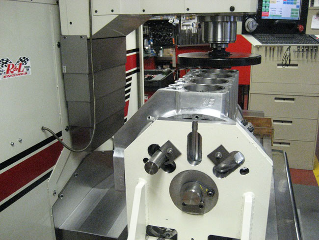
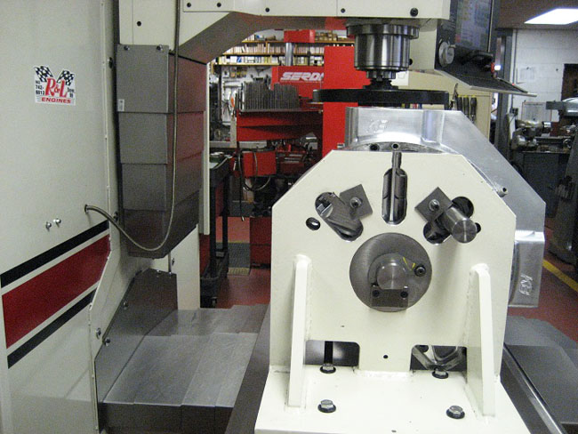
The engine block blueprinting fixture corrects improperly machined deck surfaces, commonly caused by factory machine tolerances and production line inaccuracies. This precision-machined fixture has a true 45-degree angle machined at each side of its own centerline.
The Index Datum Plate, when installed on the cam-crank centerline of the block, is then referenced to roll over and correctly index the block into position for the resurfacing operation (upper photo).
Common issues resolve after using the datum plate and CNC probe routine:
•Twisted Blocks: On a twisted block, it is necessary to choose a point on the deck surface to use as a reference point for set-up. As a result, you may be compounding the out-of-square condition.
•Uneven Deck Clearance: Deck clearance often varies between the top and bottom edges of the piston due to the deck surface not being at 90 degrees to the bore. On race engines where deck clearances are held on the verge of piston to head contact, any discrepancy in deck angle means lost compression.
•Bores Not At 90 Degrees: Since most production lines use the pan rails as the reference point, it is common to find the bores at angles other than the intended 45 degrees when referenced from the cam-crank centerline.
•Cam and Ignition Timing Variations: If you have run into cam timing variations between cylinders on opposite banks, it may not be the fault of the camshaft. Again, since most blocks are machined from the pan rails, the cylinder "V" may not be at 45 degrees when referenced from each side of the cam-crank centerline.
•O-Ring Groove Variations: If you are cutting O-Ring grooves on a boring stand which references from the pan rails, it is not uncommon to have drastic depth variations.
•Poor Intake Manifold Fit: This condition is usually blamed on the intake manifold. However, if the included angle of the deck surfaces is not 90 degrees or if the top of the block has the incorrect angle, the manifold may not be at fault.
•Block Deck-Height Measurements: CNC probe routine varifies all demension against blue print specs.
Rottler F69A CNC Engine Block Decking Surfacing & Squaring
Block blue printing is an exact science starting with the crankshaft and camshaft centerline.The block decks and cylinder bores are corrected to the crankshaft and camshaft centerline. The cylinder bores are then bored on center distances to blueprint specs. This process is achieved through the use of a datum fixture that references the crankshaft and camshaft centerline at a true 45 degrees. The block is probed from the centerline then indicated from the dowel location. This enables the bore spacing to be corrected and blue printing the deck surfaces square to the camshaft and crankshaft centerline at a true 45 degree angle is achieved..The dimensions are imputed to the CNC control holding tolerances to 0001. This accuracy is achievable with CNC machinery and specialized precision locators, and tooling.
CNC Block Decking and Squaring

