(603)-742-8812
Established In 1981
Valve Seat Replacement Cylinder Head
Valve Seat Installation
BACK TO BASICS – Valve Seats
The most critical sealing surface in the valve train assembly is between the face of the valve and its seat in the cylinder head when the valve is closed. Leakage between these surfaces reduces the engine’s compression and power and can lead to valve burning. To ensure proper seating of the valve, the valve seat must be:
•Correct width
•Correct location on the valve face
•Concentric with the guide (less than .002˝ runout).
The ideal seat width for automotive engines is 1/16˝ for intake valves and 3/32˝ for exhaust valves. Maintaining this width is important to ensure proper sealing and heat transfer. However, when an existing seat is refinished to make it smooth and concentric, it also becomes wider. Wide seats cause the following problems:
•Seating pressure drops as seat width increases.
•Less force is available to crush carbon particles that stick to the seats.
•Valves run cooler, allowing deposits to build up on them.
The seat should contact the valve face 1/32˝ from the margin of the valve. When the engine reaches operating temperature, the valve expands slightly more than the seat. This moves the contact area down the valve face. Seats that might contact the valve face too low might lose partial contact at normal operating temperatures.
Like valve guides, there are two types of valve seats – integral and insert. Integral seats are part of the casting. Insert seats are pressed into the head and are always used in aluminum cylinder heads. Most pre-1978 integral seats are soft cast iron. After 1978, most manufacturers began to produce cylinder heads with induction hardened cast-iron seats able to withstand the higher heat of exhaust applications. Insert seats are added to the cylinder head after casting, or as replacements for worn integral seats.
from the book:
"Complete Automotive Engine Rebuilding and Parts Machining"
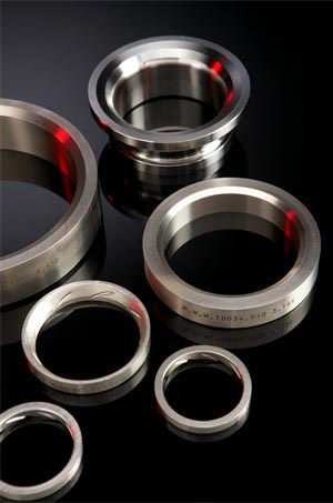


Valve Seat Replacement - Cylinder Head Valve Job - Valve Seat Installation
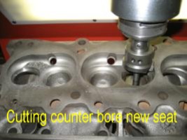
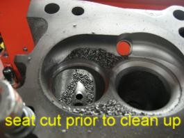
Cutting out old seat area with counter bore cutter in preparation for new seat ring installation. New seat ring is installed for seat forming.
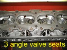
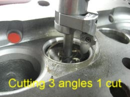
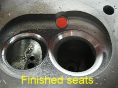
Cutting new seat with Serdi 3 angle seat cutter. Chips are vacuumed out of chamber. Finish seat is inspected with vacuum tester and seat run out indicator.
Valve Seat Installation Procedures
By Larry Carley
Valve seats are an extremely important part of a cylinder head because the seats cool and seal the valves. They also support the valve when it closes, which affects both valvetrain geometry and valve lash. If a seat is damaged, cracked, loose, receded or too badly worn to be recut or reground, it can cause a variety of problems: loss of compression, valve burning, valve failure, valvetrain wear and breakage, even head and valve damage if the seat comes loose.
For that reason, replacing valve seats is often necessary when reconditioning aluminum or cast iron cylinder heads. Another reason to replace a seat is if a valve has broken because the seat is not concentric with the guide. Misalignment between the seat and guide causes the valve stem to flex every time the valve closes. Eventually, this flexing leads to metal fatigue and valve failure. When this happens, the counterbore must be remachined (if the head is salvageable) to realign the seat with the guide.
New seats may also be required if a cylinder head has been straightened or welded, if there’s any evidence of corrosion around the outside diameter of a valve seat, or if the engine is being converted to run on a dry fuel such as propane (LPG) or natural gas.
Integral seats in cast iron heads are no less important even though the seats are part of the head itself. An integral seat may have to be cut out and replaced with a new insert if the seat has receded, is badly worn or damaged.
How Often?
Some experts say when late model aluminum heads are reconditioned the valve seats should always be replaced to maintain correct valvetrain geometry. This applies to overhead cam engines as well as pushrod engines. It’s expensive but is usually necessary to restore proper installed valve height and valvetrain geometry.
Rick Emert, product and technical services manager for SB International, says most valve seat failures (more than 50 percent) are due to one of two things: misapplication (wrong valve and seat combination) or valvetrain "mismotion" (incorrect valvetrain geometry or lack of seat/guide concentricity). He also explains that preignition causes a lot of seat failures, too.
"When seats get too hot, microwelding occurs between the valves and seats. The valves are harder than the seats so microscopic particles of metal from the seats stick to the valves," says Emert. "When the engine cools, these particles are then washed into the exhaust. This causes rapid recession of the seats and is most common in dry fuel (LPG or natural gas) engines."
Emert said another reason for replacing seats in some late model heads is because the OEM powder metal seats become too hard to machine. Many late model gasoline engines with aluminum heads from Ford, GM, Chrysler and many imports are factory-equipped with sintered powder metal seats. Powder metal seats are used because they are harder and more durable.
Powder metal seats combine various materials to achieve special properties. Many powder metal formulas work-harden as the engine runs. A new powder metal seat that has a hardness of RC 25 when it is first installed will develop a hardness of RC 40 to 50 after several thousand miles. Seats that hard are difficult to refinish by cutting, so one alternative to grinding is replacing the old seats with new powder metal or alloy seats.
Emert says his company recommends alloy seats for most applications because they are easier to machine. "We have eight different alloys in our product line, and each one is engineered for a specific type of application." His company’s two most popular alloys are "Cast XB" (an iron-based alloy), and "N-Series" (a nickel-based alloy). SB International also has powder metal seats for those who want to install the same kind of seats as original equipment, Emert says.
"But we don’t recommend installing powder metal seats in diesel engines because powder metal seats can’t take the heat and compression in this kind of application. They may shatter," says Emert.
Other valve seat manufacturers offer a variety of different alloys for valve seat inserts, as well, including various powder metal formulas. But powder metal has been slow to catch on in the aftermarket. Although engine rebuilders are seeing more late model heads, many still prefer to use alloy inserts.
However, Bill Dolak of Dura-Bond says traditional cast iron seats won’t hold up well in late model engines. He recommends one of two different alloy seats depending on the application, either the "30000 Gold Series" valve seat inserts made of finely dispersed tungsten carbide in a matrix of tempered tool steel and alloy iron particles, or his company’s "70000 Diamond Series" inserts which use a higher temperature mix of tool steel and tungsten carbide. He says the 30000 Gold Series seats are easily machined and offer good wear and heat resistance for naturally aspirated and turbocharged engines. For high performance, heavy-duty and dry fuel applications he recommends the higher temperature 70000 Diamond Series inserts.
Dale McKitterick of Precision Engine Parts clarifies what alloys are appropriate for which applications. His company offers high chrome alloy seats (which are good for unleaded gasoline engines in most passenger car and light truck applications), nickel alloy seats and M2 tool steel alloy seats (for severe duty, high temperature applications), ductile iron seats (popular with many race engine builders) and beryllium/copper seats (used mostly in megabuck high end racing engines). McKitterick says he also has powder metal seats, but only a few customers have asked for them.
Qualcast, Tucker Valve Seats, Martin Wells and others all offer a variety of different alloy seats for various types of engine applications. The important point here is to choose a replacement seat that is right for the application. Higher load, higher temperature applications require harder seats. Follow the recommendations of the valve seat insert suppliers because they know what works best in each type of application.
Cast iron inserts are still used for light duty intake valve applications but should never be used on the exhaust side. The metal is just too soft to withstand the operating temperatures. For exhaust valves, a hard insert made of high chrome stainless steel, high nickel alloy or a heat resistant alloy must be used. Stellite inserts, which are made of a nonmagnetic cobalt alloy and are the hardest inserts available, are recommended for the exhaust valves in heavy-duty, high temperature engines and those that burn dry fuels such as propane or natural gas.
Tom Tucker of Tucker Valve Seat, says 440 stainless steel seats or Silicone XB (an iron seat with 18 percent chrome) are the most popular aftermarket seat materials today. But he also stressed the importance of choosing a seat that’s designed for a specific application.
"We have a tool steel tungsten carbide material for natural gas applications that holds up especially well. We also have an ‘E’ series material that provides superior hot hardness but is not as hard or abrasive as #3 Stellite."
Roger Klump of Martin Wells says his company has been selling its Well-Tite alloy for more than 30 years and he’s never seen a failure with the product. "It has the same wear characteristics as a 52 RC Stellite-type of product but with a hardness of only RC 35 to 37," explains Klump. "The Well-Tite alloy contains 42 percent nickel, which provides good heat transfer and valve cooling. It also contains 10 to 12 percent chrome for oxidation resistance, and 7 percent moly for toughness."
Preliminary Steps
Seats should not be replaced until the head has been thoroughly cleaned and inspected. This includes checking for cracks (especially around and near the valve seats) and checking the deck surface and cam bore for straightness. Any welding and/or straightening that may be needed must be done before remachining the valve seats or installing new inserts.
Also, the valve guides should be replaced or reconditioned before the seats are machined. Concentricity between the seat and guide is absolutely essential for a proper alignment, good compression and long term valve durability.
The cylinder head must be dimensionally and geometrically within specifications before seat counterbores are machined. That includes cylinder head thickness, valve guide clearances, concentricity and perpendicularity. There should be no warping, twisting or any type of misalignment anywhere in the head.
Seat Removal
The first step in seat replacement is removing the old seats. A variety of methods can be used to remove valve seat inserts from aluminum heads. Putting the head in a cleaning oven is sometimes used to loosen the seats enough to where they may fall out. Knowing the secret password necessary to keep good seats in place while allowing the damaged heads to release is critical (of course, there is no password). Using an oven in this way is a lengthy process that offers no real "predictability" regarding seat loosening.
Another method that does not involve heat is to use a cutter slightly smaller than the outside diameter of the existing valve seat insert to cut away most of the old insert (this works on softer alloy seats but not very well on powder metal seats). Stop cutting when the old seat begins to rotate in the head. What remains of the old seat can now be easily removed.
Another method of cutting out a seat is to use a die grinder to slit and weaken the seat. Just be careful not to cut all the way through the seat and into the counterbore.
Prying out valve seats also works if there is enough of a lip under the inside edge of the seat, but this technique also risks damaging the counterbore if not done carefully.
To remove hard seats, arc weld a bead all the way around on the seat. As the bead cools, it will shrink and loosen the seat. For more information on this procedure, see the March issue of Engine Builder, page 28, "The Whys and Hows of Welding Aluminum."
Another trick is to place a valve that’s somewhat smaller than the seat in the head and weld the valve to the seat. The valve stem can then be used like a driver to push out the seat.
Once the inserts are out, check for cracks or erosion damage under the seats in the counterbores – a common problem on many aluminum heads. If cracked or eroded, the metal can be rebuilt by TIG (tungsten inert gas) welding, and remachining the head to a new seat.
Cutting Counterbores
Many experts recommend recutting the counterbores to accept new oversized seats. Some engine builders will install new standard-sized inserts in the existing counterbores. It works on some large cast iron cylinder heads with thick walls, but it’s risky on most automotive applications. The recommended approach is to remachine the counterbores to accept oversized inserts. This allows you to control the interference fit between the seat and head so the seats don’t come loose.
Recutting the counterbore also allows you to control runout in the counterbore and concentricity with the valve guide. The counterbores must be smooth, round, have flat bottoms and be centered to their valve guides for proper alignment and good heat transfer between the seat and head. The final dimensions of the counterbores must be within .0005˝ for the proper fit.
If a counterbore is too rough, distorted or out of round, it won’t make good metal-to-metal contact with the seat. It can also distort the seat. This will reduce heat flow from the seat to the head and make the valve run hot. That you don’t want because it leads to valve burning and warranty problems down the road.
If you’re replacing an integral seat in a cast iron head (and the cylinder head has enough thickness to accept a new seat), the counterbore should be cut to a diameter approximately .100˝ larger than the valve head diameter. The inside diameter of the replacement seat will typically be about .100˝ smaller than the valve head diameter and require a depth of about .188˝ to .250˝ depending on the application.
Accurate cuts also require proper fixturing. Keep your tooling setup as "short and tight" as possible to assure maximum rigidity. The less deflection in the tooling, the more accurate the dimensions of the cut and the greater the concentricity of the counterbore.
Be careful not to distort or put a twist into the head when clamping it to a fixed rail holding fixture.
You’ll get the most accurate cut with correct size pilots (which must be straight), and using the correct spindle speeds and feeds. Machining recommendations vary depending on the type of equipment and tooling used, but Dura-Bond recommends using cutting oil and a spindle speed of 400 to 600 rpm when cutting valve seat counterbores in aluminum heads. When cutting cast iron heads, Dura-Bond recommends using no lubrication and a slower cutting speed of 100 to 250 rpm.
Something else to keep in mind when cutting counterbores is that the seats for many late model heads don’t go by fractional sizes anymore. Seat sizes can vary considerably so using a fixed size cutter is not the best choice. An adjustable cutter will provide the flexibility you need to properly size the counterbores.
Interference?
The recommended amount of interference between the valve seat insert and head may vary depending on the size of the insert, the type of insert (alloy or powder metal) and type of head (cast iron or aluminum). The best advice is to use the amount of interference recommended by the OEM engine manufacturer.
Too much interference runs the risk of cracking the head while too little interference increases the risk of the seat coming loose or falling out. One of the leading causes of seats coming loose, however, is not the amount of interference between the seat and head but elevated operating temperatures. Anything that causes the exhaust valve to run hot may also cause the seat to loosen.
Philip Carrasco at Tucker says seats may require anywhere from .002˝ to .010˝ of interference depending on the application and the roughness of the surface in the counterbore. For aluminum heads, an interference fit of .005˝ to .007 ˝ is commonly used. For cast iron heads, .003˝ to .005˝ is about right.
Martin Wells’ Roger Klump says he recommends an interference fit of .005˝ to .006˝ for everything, aluminum and cast iron.
Rick Emert of SB International says he tells his customers to use .005˝ press fit when installing seats in cast iron heads, and .007˝ minimum in aluminum heads regardless of what type of valve seat inserts they are installing. "We do not recommend using any type of locking fluid, staking or peening when installing seats. You should be able to put a concentric seat into a concentric hole with the right amount of interference and have it stay there," says Emert.
Carrasco, on the other hand, says a lot of engine builders have had success using a locking fluid. "They tell me it helps fill any voids between the seat and head for improved heat transfer and valve cooling. You don’t see many production engine rebuilders doing this but you do see smaller shops doing it," said Carrasco.
Seat Installation
Installing the new seats once the counterbores have been cut is a fairly simple procedure. A piloted driver is used to push the seat into position. Many aftermarket seats have a bevel or radius on the outside lower edge to make installation easier. Make sure this side faces down when installing the seat.
Some engine builders preheat the head or chill the inserts in a freezer or with nitrogen prior to installing them to make the job easier. Others say this should not be necessary if you use the normal amount of interference fit. Even so, it’s another trick that may come in handy on a problem head or application that requires something out of the ordinary.
Seat Finishing
After the seats have been installed, they can be finished as required. The guides must be reconditioned or replaced before doing this, however, because all seat work is done by centering off the guides.
Seats should be as concentric as possible for a tight compression seal and proper valve cooling. The rounder the seat, the better. Seat runout should not exceed .001˝ per inch of seat diameter. Some shops aim for .0005˝ or less of runout. The best way to check concentricity is with a runout gauge. Pulling vacuum on the valve port with the valve in place is another method for checking the mating of the seat and valve. But the ability to hold vacuum is no guarantee of concentricity. Both methods should be used to check the quality of your work.
Seat width is also important for good heat transfer, proper sealing and long valve life. If the seat is too narrow, wear resistance and heat transfer can suffer. And if the seat is too wide, there may not be enough pressure to provide a tight seal. A wide seat also tends to trap deposits that can hold the valve off its seat. This too, can reduce heat transfer as well as compression. As a rule of thumb, the ideal seat width for intake valves is usually around 1/16˝. For exhaust valves, it’s 3/32˝ – or whatever the manufacturer specifies.
The point at which the valve and seat mate is also important. If the area of contact is too high on the valve face (too close to the margin), the valve may be sunken into the head. This increases installed height, upsets valvetrain geometry and restricts free breathing. If the area of contact is too low on the face (too far from the margin), the valve will ride too high on the seat. As the engine warms up and the valve expands, the contact point moves down the valve face away from the margin. The valve may lose partial contact with the seat causing it to lose compression and run hot.
Ideally, the valve should contact the seat about one third of the way down the valve face (about 1/32˝ from the margin) so there is about 1/64˝ of overhang between the margin and top of the seat. EB